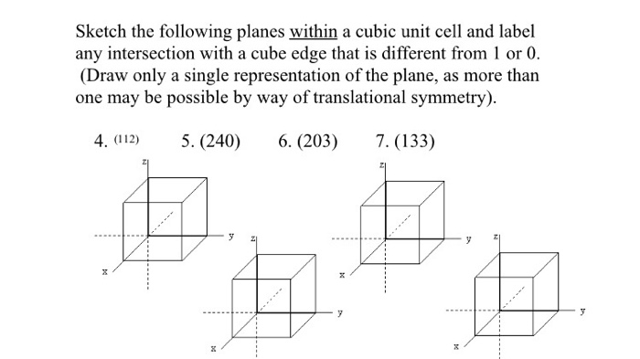
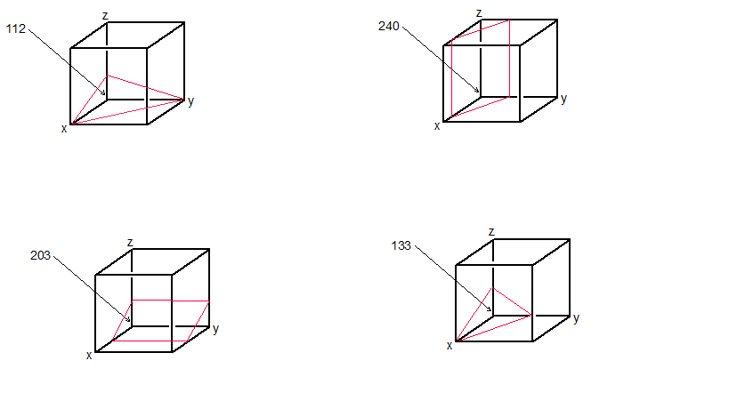
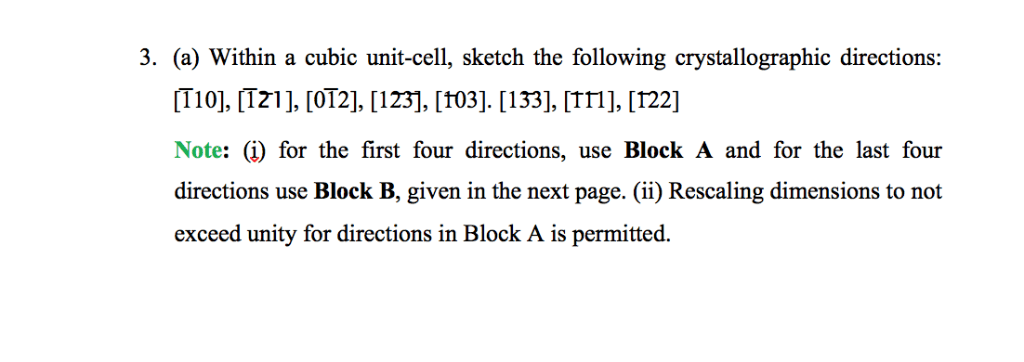
Within a cubic unit cell sketch the following directions introduces the concept of crystallographic directions and their representation using Miller indices. This guide provides a comprehensive overview of common crystallographic directions, their vector representation, and a step-by-step approach to sketching them within a cubic unit cell.
Understanding crystallographic directions is crucial for analyzing crystal structures, predicting material properties, and designing materials with specific functionalities.
Crystallographic Directions within a Cubic Unit Cell: Within A Cubic Unit Cell Sketch The Following Directions

In crystallography, crystallographic directions refer to the specific orientations of atomic arrangements within a crystal lattice. Within a cubic unit cell, these directions are defined using the Miller indices notation.
Miller Indices Notation
The Miller indices are a set of three integers, (h, k, l), that represent a specific crystallographic direction. These indices are determined by finding the intercepts of the direction with the three crystallographic axes (a, b, c). The reciprocals of these intercepts, multiplied by the smallest integers that give integer values, are the Miller indices.
Common Crystallographic Directions
Some common crystallographic directions in a cubic unit cell include:
- [100]: Along the x-axis
- [010]: Along the y-axis
- [001]: Along the z-axis
- [110]: Diagonal in the xy-plane
- [111]: Diagonal through the cube
These directions are related to the lattice vectors of the cubic unit cell as follows:
- [100] = a
- [010] = b
- [001] = c
- [110] = (a + b) / 2
- [111] = (a + b + c) / √3
Vector Representation
Crystallographic directions can also be represented as vectors. The direction vector is given by:
d = h*a + k*b + l*c
where a, b, and c are the lattice vectors and h, k, and l are the Miller indices.
The direction cosines of a vector are the cosines of the angles between the vector and the three crystallographic axes. They are given by:
- cos α = h / √(h^2 + k^2 + l^2)
- cos β = k / √(h^2 + k^2 + l^2)
- cos γ = l / √(h^2 + k^2 + l^2)
Sketching Crystallographic Directions
To sketch a crystallographic direction within a cubic unit cell:
- Draw the cubic unit cell.
- Identify the Miller indices of the direction.
- Plot the intercepts of the direction with the three crystallographic axes.
- Connect the intercepts to form the direction vector.
For example, to sketch the [110] direction, draw a cube and plot the intercepts at (1, 0, 0), (0, 1, 0), and (0, 0, 1). Connect these points to form the diagonal in the xy-plane.
Additional Considerations, Within a cubic unit cell sketch the following directions
When sketching crystallographic directions, it is important to consider the symmetry of the crystal. The direction vector should be drawn in a way that reflects the symmetry of the crystal lattice.
Fractional coordinates can also be used to represent directions. Fractional coordinates are the ratios of the intercepts of the direction vector with the unit cell edges. For example, the [110] direction can be represented as (1/2, 1/2, 0) in fractional coordinates.
Quick FAQs
What are crystallographic directions?
Crystallographic directions are vectors that describe the orientation of atomic rows or planes within a crystal lattice.
How are crystallographic directions represented using Miller indices?
Miller indices are a set of three integers that represent the intercepts of a crystallographic direction with the unit cell axes.
What is the relationship between crystallographic directions and lattice vectors?
Crystallographic directions are parallel to lattice vectors, which are vectors that connect lattice points in a crystal.

